Custom Case Study
A customer’s design required a bank of polymer tantalum capacitors to achieve the necessary power level, but was restricted by a limited PCB area. However, the design offered available height that could be used if an appropriate solution could be found.
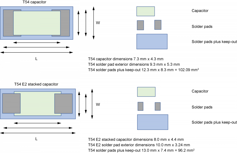
It should be noted that apart from the specific length and width of a capacitor, and the footprint of the recommended solder pad dimensions, there are also “keep-out” areas on a PCB that can’t be used in order to prevent mechanical and electrical interference.
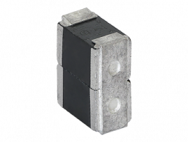
To address this problem, the Vishay engineering team developed a stacked capacitor assembly solution that vertically mounted multiple T54 series polymer tantalum capacitors using a flexible mechanical termination design. Structurally, the metal termination that was developed for the stack also provided very robust shock and vibration performance while addressing heatsink considerations.
When considering utilizing board area, there are various measurements involved. These include the dimensions of the capacitor itself (L x W); the PCB recommended pad dimensions required for assembly, which typically occupy more PCB area for individual chips; and the manufacturer’s recommended “keep-out” area.
EXAMPLE
For a 940 µF, 16 V solution, the occupied PCB area, including the “keep-out” area (3 mm), is:
|
Two T54 470 µF at 16 V |
204.18 mm2 |
|
T54 E2 stack 940 µF at 16 V |
96.2 mm2 |
|
PCB \area savings |
107.98 mm2 or 52.9% |
Since this double-stack (two-capacitor) solution was developed, Vishay has further expanded this range to offer combinations of three, four, and six T54 series devices that provide much higher overall capacitance values.

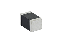
T54EE

T54E2

Mechanically, the stacking of T54 polymer capacitors allowed our customer to significantly increase the capacitance density available for the given PCB area. Our custom solution took advantage of the height available by minimizing part placement on the linear plane and provided 35.6 % space savings.
Using this mechanical design also provides additional electrical performance enhancements. Mounting multiple capacitor devices in parallel reduces the overall capacitor ESR performance value. For example, putting two devices in this stacked solution reduces the ESR by 50 %. So, assembling two 50 mΩ devices will result in a 25 mΩ, two-capacitor assembled stack. In addition, the nominal capacitance and tolerances applied during the testing of individual parts means the assembled unit can sometimes be rated with a slightly higher combined total capacitance. For example, combining two 220 µF T54 series parts results in a 450 µF assembly.
There are also other mechanical advantages of using the stacked capacitor terminations. They include better heatsinking and more robust shock and vibration performance.
Please fill out the form and submit to get started.


