INTRODUCTION TO THE PIEZO RESISTIVE SENSOR BRIDGE TEMPERATURE COMPENSATION TOOL
A very common type of pressure sensor consists of diaphram with piezoresistive strain gauges resistors diffused into it, fused to a silicon or glass backplate. This support tool helps the designer determine the appropriate values for the thermistor and fixed resistors used to implement this circuit. The network obtained will bias the voltage applied to a piezoresistive bridge compensating the output voltage of this bridge.
The tool gives the user the option to choose either a voltage source or current source. Next, the user should define the temperature range (between -55 °C and 150 °C). The limits defined here are very important as a narrow temperature range will automatically lead to a better fitting solution
The user has the option to choose what type of mechanical execution is needed for the NTC thermistor (leaded or SMD 0402, 0603, or 0805 case). The user will enter the value of the power supply and piezoresistive element, its temperature coefficient of resistance (TCR), and finally, the loss of sensitivity of the bridge output voltage as a function of the temperature coefficient of sensitivity (TCS). Five points within the temperature range will be used in order to identify the best fitting values for the thermistor and fixed resistors.
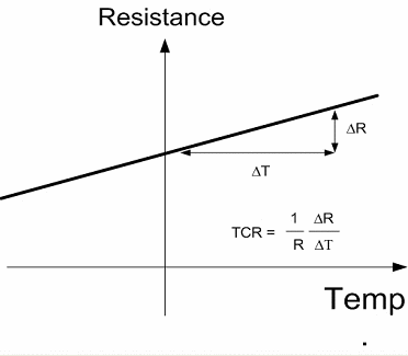
What is the TCR of a Piezo-resistive Sensor?

Just like any resistor, a strain gauge sensor has an electrical resistivity value which changes with temperature. The TCR or temperature coefficient is expressed as a percentage change of resistance versus temperature in units of % per °C (typically between +0.14%/°C and +0.26%/°C).
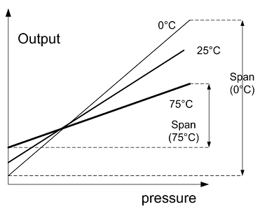
What is the TCS of a Piezo-resistive Sensor?

The output voltage of the piezo-resistive sensor changes proportionally with the differential pressure. However, the voltage span decreases with the temperature. As a consequence, the sensitivity decreases with temperature (typically between -0.11%/°C and -0.21%/°C).
The part number of the thermistor will be defined after optimization, the optimal value will be displayed together with fixed resistor values (selected from E12, E48, and E96 series). The user will have option to define thermistor R25 tolerance depending on the required fitting level.
Click here for schematic cross-section of the basic elements of a silicon piezoresistor.
![]()
The simplest form of piezo-resistive silicon sensors are diffused resistors. Piezo-resistors consists of a simple two-contact diffused n-type or p-type wells within a p-type or n-type substrate diaphram, in contact with a silicon support wafer. The external pressure is transmitted to the diaphram through a pressure port.
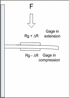
Click here for schematic cross-section of how resistors can be in compression or in extension on the same substrate.

Under the effect of mechanical force (or pressure), the strain gauge on the above surface of the carrier is in extension with a positive R drift. The gauge at the other side is in compression and exhibits the same resistance drift but in the negative direction. This combination can double the sensitivity of the measurement.
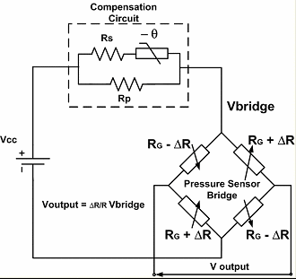
Click here for sample schematic diagram of a four arm Wheatstone Bridge and a compensation network.

The circuit shows how the four arms of the bridge (two arms are in extension, and the other two arms are in compression) are connected with each other in order to enhance the sensitivity of V-output. The total resistance of the bridge remains equal to R and does not change with the pressure. However, it will depend on the temperature with a defined TCR (temperature coefficient of resistance), influencing the value of the V-bridge. Moreover, the ΔR is also dependent on temperature and induces of losses in sensitivity of V-output in function with temperature TCS (temperature coefficient of sensitivity). The thermistor-resistor network will be adjusted to maintain V-output constant in function with temperature.


