


Custom Case Study
Our customer was evaluating a solution for power electronics equipment that required the use of several DC-Link capacitors on the same PCB, while ensuring that the devices would support critical vibration profiles.
The products being considered for the application had a significantly high mass of around 100 g, and were attached to the PCB via four lead wires with 1.2 mm diameters. While testing these parts under severe vibration profiles, the customer reported broken lead wires.
The challenge was clear: how can such high mass parts withstand severe vibration profiles, while maintaining a similar footprint on the PCB?
Standard MKP1848 series DC-Link capacitors are supplied with lead wire diameters adjusted to the devices’ mass — from 0.8 mm for products with lead spacing of 27.5 mm, up to 1.2 mm for 52.5 mm lead spacing. On larger devices, four pins are also a standard feature. If properly clamped, this type of through-hole technology (THT) terminal is sufficient to withstand the vibration profiles described in general industry standards. However, to address our customer’s challenge, where the requirements exceeded the afore-mentioned standards, a more robust connection was needed to improve the capacitor’s grip on the PCB.
As a solution, the four lead wires of the DC-Link capacitors were replaced with two 1 mm tin-platted copper tabs. The perimeter of these tabs was over four times higher when compared with the original four pins, and section area was tripled. This led to a much higher contact area between the terminal and solder on the PCB, ruggedizing the connection as intended.
At the same time, all other electrical and robustness characteristics of the capacitors were validated and tested to demonstrate that the copper tab solution would not jeopardize either of them. The devices maintained their AEC-Q200 compliance and preserving THB characteristics for high robustness under high humidity products.
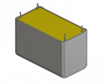
Standard DC-Link Capacitor
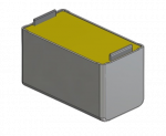
Tab Terminal DC-Link Capacitor
Prototypes were submitted to several vibration tests with different acceleration rates, frequencies, and amplitudes across the three axis. The testing showed significant improvement with the usage of tab terminals versus lead wires, and that our goal of offering the customer a DC-Link film capacitor that was able to support harsh vibration profiles was successfully accomplished.
The DC-Link film capacitors with tab terminals remain THT components. This allows the devices to be soldered to the PCB by conventional methods, preventing the need for any special processes to achieve a ruggedized fixation. The external dimensions of the capacitors are also maintained when compared with the original four-pin version, resulting in minimal design changes on the PCB. Only the holes and soldering pads needed to be changed to fit the new terminals.
Furthermore, this robust connection also improves ripple current capabilities through the capacitor, as the terminal section is improved while its resistivity drops, allowing for better power dissipation. This enhances the power density for the DC-Link capacitors.
Please fill out the form and submit to get started.


